4.10 – Excavation
20.78 Work standards
- Subject to this section, excavation work must be done in accordance with the written instructions of a qualified registered professional if
- (a) the excavation is more than 6 m (20 ft) deep,
- (b) an improvement or structure is adjacent to the excavation,
- (c) the excavation is subject to vibration or hydrostatic pressure likely to result in ground movement hazardous to workers, or
- (d) the ground slopes away from the edge of the excavation at an angle steeper than a ratio of 3 horizontal to 1 vertical.
- Despite subsection (1), excavation work described in that subsection must be done in accordance with the written instructions of a professional engineer if the excavation requires or uses support structures.
- The written instructions required by this section must
- (a) be certified by the qualified registered professional concerned,
- (b) be available at the site, and
- (c) specify the support and sloping requirements, and the subsurface conditions expected to be encountered.
20.79 Underground utility services
- Before excavating or drilling with powered tools and equipment, the location of all underground utility services in the area must be accurately determined, and any danger to workers from those utility services must be controlled.
- Excavation or drilling work in proximity to an underground utility service must be undertaken in conformity with the requirements of the owner of that utility service.
- Pointed tools must not be used to probe for underground petroleum and electrical utility services.
- Powered equipment used for excavating must be operated so as to avoid damage to underground utility services, or danger to workers.
20.80 Removing nearby hazards
Trees, utility poles, rocks and similar objects adjacent to an area to be excavated must be removed or secured if they could endanger workers.
20.81 Sloping and shoring requirements
- Subject to section 20.78, before a worker enters any excavation over 1.2 m (4 ft) in depth or, while in the excavation, approaches closer to the side or bank than a distance equal to the depth of the excavation, the employer must ensure that the sides of the excavation are
- (a) sloped as specified in writing by a qualified registered professional,
- (b) sloped at angles, dependent on soil conditions, which will ensure stable faces, but in no case may the slope or combination of vertical cut and slope exceed that shown in Figure 20-1,
- (c) benched as shown in Figure 20-2,
- (d) supported as specified in writing by a professional engineer,
- (e) supported in accordance with the minimum requirements of section 20.85, or
- (f) supported by manufactured or prefabricated trench boxes or shoring cages, or other effective means.
- If the end of a trench over 1.2 m (4 ft) in depth is not adequately sloped, end shoring must be installed unless
- (a) a worker in the trench is not required to approach closer to the end of the trench than a distance equal to the depth of the trench at that end,
- (b) where, for the prevailing soil conditions at the end of the trench, the permissible spacing of uprights equals or exceeds the width of the trench, or
- (c) otherwise authorized in writing by a professional engineer or professional geoscientist.
- If end shoring is required, the walers for the end shoring must be installed to bear against the walers that extend along the sides of the trench, or in a manner that will provide equivalent structural restraint.
- End shoring must be designed by a professional engineer if the end shoring waler length exceeds 1.8 m (6 ft).
- Shoring must extend from at least 30 cm (1 ft) above ground level to as close to the bottom of the trench as the material being installed will allow, but in no case more than 60 cm (2 ft) from the bottom.
- Shoring need not extend above ground level where traffic crossing plates need to be used, provided that other measures are taken to prevent excavated or other material from entering the excavation.
20.82 Timber shoring and grades
- Timber shoring materials must be lumber graded Number 2 or better from the following species groups: Douglas fir-larch, hemlock-fir, spruce-pine-fir or coast-Sitka-spruce.
- All lumber must be graded to the National Lumber Grades Authority Standard Grading Rules for Canadian Lumber.
20.83 Safe shoring procedures
- Shoring materials must be installed from the top down and removed in reverse order.
- Workers must not enter an excavation to remove shoring materials if ground conditions have deteriorated so as to make entry for shoring removal unsafe.
- Shoring or manufactured or prefabricated support systems must be installed in firm contact with the faces of the excavation, and in a manner, which ensures no loss of soil from behind or below the bottom of the shield or shoring while the excavation is open.
- Unless otherwise indicated by the manufacturer or a professional engineer, in writing, voids between the shoring and the excavation face must be backfilled or blocked.
20.85 Trench support structures
| Soil type | Description of soil |
| A | hard and solid |
| B | likely to crack or crumble |
| C | soft, sandy, filled or loose |
| Depth at location | Number of braces |
| up to 2.4 m (8 ft) | 2 |
| 2.4 m to 3.7 m (8 ft to 12 ft) | 3 |
| 3.7 m to 4.6 m (12 ft to 15 ft) | 4 |
| 4.6 m to 6 m (15 ft to 20 ft) | 5 |
- Trench support structures, other than those designed by a professional engineer, must comply with Table 20-1 for the following relevant soil conditions:
- If Table 20-1 is to be used for a combination of supporting and sloping, the selection of shoring elements must be based on the overall depth of the excavation, and the arrangement must conform to Figure 20-3.
- Cross braces and trench jacks must be installed in a horizontal position and must be secured against dislodgment.
- The minimum number of cross braces at each cross-bracing location is determined by the trench depth as follows: (Depth at location table)
- At each cross-bracing location, the cross braces must be less than 1.2 m (4 ft) apart, and the uppermost cross brace must be within 60 cm (2 ft) of ground level.
- Repealed. [B.C. Reg. 312/2003, effective October 29, 2003.]
- Hydraulic or pneumatic trench jacks must have a means of ensuring that they will not collapse in the event of loss of internal pressure.
- Uprights must not spread outwards more than 15 degrees from the vertical when viewed along the trench.
- Plywood may be substituted for 2” thick shoring elements provided that
- (a) the plywood is not less than 19 mm (3/4 in) thick,
- (b) the trench is not over 2.7 m (9 ft) in depth,
- (c) uprights are installed at not over 60 cm (2 ft) centres,
- (d) cross braces do not bear directly on plywood, and
- (e) cross braces bearing on uprights or walers are located at all joints in plywood sheathing.
20.86 Spoil piles
If the average depth of a spoil pile which is adjacent to a supported excavation exceeds 60 cm (2 ft), the selection of the shoring or shielding must take into account the resulting increase in lateral soil pressure.
NOTE: Table 20-1 includes an allowance for 60 cm (2 ft) of spoil pile adjacent to the excavation. In such cases shoring or shielding will be deemed acceptable if rated adequate for a tabulated depth equal to the depth of the excavation plus the average depth of the spoil pile minus 60 cm (2 ft). For other systems consult the manufacturer’s instructions.
20.87 Entry and exit
- Safe means of entry and exit must be provided for an excavation a worker enters.
- If workers are required to enter a trench over 1.2 m (4 ft) deep, the safe point of entry and exit must be located within 8 m (25 ft) of the workers and the excavation must be safely supported or sloped to the entry and exit location.
- Walkways must be secured to prevent dislodgment.
- The open side of an access route into an excavation used by mobile equipment must have a curb.
20.88 Guarding
If an excavation is a hazard to workers, it must be effectively covered or guarded.
20.89 Excavation crossings
A walkway across an excavation must be at least 50 cm (20 in) wide, and if crossing an excavation over 1.2 m (4 ft) deep, be equipped with guardrails, meeting the requirements of Part 4 (General Conditions), on both sides.
20.90 Excavated materials
- Excavated material must be kept back a minimum distance of 60 cm (2 ft) from the edge of a trench excavation and 1.2 m (4 ft) from any other excavation.
- Under no circumstances may excavated material be piled so that it endangers workers.
20.91 Use of skips or buckets
If a skip or bucket is used to remove material from an excavation, horizontal shoring members must be shielded from dislodgment with vertical planking.
20.92 Scaling and trimming
The sides of an excavation must be scaled and trimmed or otherwise stabilized to prevent slides of material or falls of rock which could endanger workers.
20.93 Height limitations
In pits, quarries and similar excavations the height of unstable faces must not exceed the maximum safe reach of the excavating equipment being used.
20.94 Positioning equipment
Whenever possible, power machines excavating banks must be positioned so that the operator is on the side away from the bank and with the boom positioned closest to the side of the excavation.
20.95 Water accumulation
- Water must not be allowed to accumulate in an excavation if it might affect the stability of the excavation or might endanger workers.
- Erosion of slopes by surface water must be prevented if workers may be endangered.
Table 20-1: Trench support structures
| Size and spacing of members1 (metric figures) | ||||||||
| UPRIGHTS | WALERS | CROSS BRACES | ||||||
| Trench depth (m) | Min dimensions (mm)2 | Max spacing (m) | Min dimensions (mm)2 | Max vertical spacing (m) | width of trench (m) | Max spacing (m) | ||
| Up to 1.8-1.8-3.7 | ||||||||
| Min dimensions (mm)2 | ||||||||
| Vertical | Horizontal | |||||||
| Type A: Hard and solid soil | ||||||||
| 1.2-3 3 | 38 x 235 | 1.8 | 89 x 140 | 1.2 | 89 x 89 | 140 x 140 | 1.2 | 1.8 |
| 3-4.6 | 38 x 235 | 1.2 | 140 x 140 | 1.2 | 89 x 140 | 140 x 191 | 1.2 | 1.8 |
| 4.6-6 | 38 x 235 | Close tight | 140 x 140 | 1.2 | 140 x 191 | 191 x 191 | 1.2 | 1.8 |
| Type B: Soil likely to crack or crumble | ||||||||
| 1.2-3 3 | 38 x 235 | 1.2 | 89 x 140 | 1.2 | 89 x 140 | 140 x 140 | 1.2 | 1.8 |
| 3-4.6 | 38 x 235 | 0.9 | 140 x 191 | 1.2 | 140 x 140 | 140 x 191 | 1.2 | 1.8 |
| 4.6-6 | 38 x 235 | Close tight | 140 x 191 | 1.2 | 140 x 191 | 191 x 191 | 1.2 | 1.8 |
| Type C: Soft, sandy, filled or loose soil | ||||||||
| 1.2-3 3 | 38 x 235 | Close tight | 140 x 191 | 1.2 | 140 x 140 | 140 x 191 | 1.2 | 1.8 |
| 3-4.6 | 38 x 235 | Close tight | 191 x 191 | 1.2 | 140 x 191 | 191 x 191 | 1.2 | 1.8 |
| 4.6-6 | 64 x 235 | Close tight | 191 x 241 | 1.2 | 140 x 191 | 191 x 241 | 1.2 | 1.8 |
| Size and spacing of members1 (imperial figures) | ||||||||
| UPRIGHTS | WALERS | CROSS BRACES | ||||||
| Trench depth (feet) | Min dimensions (inches)2 | Max spacing (feet) | Min dimensions (inches)2 | Max vertical spacing (feet) | width of trench (feet) | Max spacing (feet) | ||
| Up to 6-6-12 | ||||||||
| Min dimensions (inches)2 | ||||||||
| Vertical | Horizontal | |||||||
| Type A: Hard and solid soil | ||||||||
| 4-10 3 | 2 x 10 | 6 | 4 x 6 4 | 4 | 4 x 4 | 6 x 6 | 4 | 6 |
| 10-15 | 2 x 10 | 4 | 6 x 6 | 4 | 4 x 6 | 6 x 8 | 4 | 6 |
| 15-20 | 2 x 10 | Close tight | 6 x 6 | 4 | 6 x 8 | 8 x 8 | 4 | 6 |
| Type B: Soil likely to crack or crumble | ||||||||
| 4-10 3 | 2 x 10 | 4 | 4 x 6 | 4 | 4 x 6 | 6 x 6 | 4 | 6 |
| 10-15 | 2 x 10 | 3 | 6 x 8 | 4 | 6 x 6 | 6 x 8 | 4 | 6 |
| 15-20 | 2 x 10 | Close tight | 6 x 8 | 4 | 6 x 8 | 8 x 8 | 4 | 6 |
| Type C: Soft, sandy, filled or loose soil | ||||||||
| 4-10 3 | 2 x 10 | Close tight | 6 x 8 | 4 | 6 x 6 | 6 x 8 | 4 | 6 |
| 10-15 | 2 x 10 | Close tight | 8 x 8 | 4 | 6 x 8 | 8 x 8 | 4 | 6 |
| 15-20 | 3 x 10 | Close tight | 8 x 10 | 4 | 6 x 8 | 8 x 10 | 4 | 6 |
1 The dimensions shown are minimum and must be increased if necessary to meet job conditions.
2 The dimensions of members in millimetres are actual dimensions for surfaced dry materials. The dimensions in inches are the nominal values for surfaced dry materials.
3 Trenches less than 1.2 m (4 ft) deep must be shored when hazardous ground movement may be expected, as in ground subject to hydrostatic pressure or vibration.
4 Walers may be omitted in trenches not exceeding 2.4 m (8 ft) in depth provided that it has been confirmed that the soil is sufficiently hard and solid to safely permit waler deletion, and provided that the trench is not in proximity to previously excavated ground.
Figure 20-1: Sloping in lieu of shoring
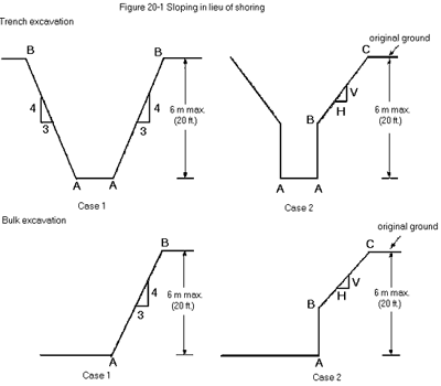
Case 1 (trench or bulk excavation) – maximum slope of excavated face, shown as line AB, in hard and solid soil is 3 horizontal to 4 vertical.
Case 2 (trench or bulk excavation), maximum height of vertical portion, shown as line AB is 1.2 metres (4 feet).
For Case 2 (trench or bulk excavation), the maximum permissible slope of the excavated face BC for the corresponding height of the lower vertical cut AB is as follows:
| Height of line AB | Maximum slope of line BC | |
| centimetres | feet | (in hard and solid soil) |
| up to 30 | up to 1 | 1 horizontal (H) to 1 vertical (V) |
| 30 to 60 | 1 to 2 | 3H to 2V |
| 60 to 90 | 2 to 3 | 2H to 1V |
| 90 to 120 | 3 to 4 | 3H to 1V |
Figure 20-2: Benching in lieu of shoring
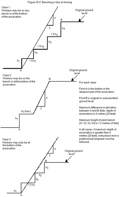
Figure 20-3: Combined supporting and sloping
